This is the third blog post in our four-part educational series about pumps and irrigation pumping.
We’re building a knowledge base for energy and water efficiency in the agricultural industry, in order to make the most of our energy and water resources. The first two blog posts laid the groundwork about the basics of fluids and fluid mechanics, and provide a basic understanding of pumps and irrigation operations:
- Pumping 101: How Irrigation Pumps Move Water (Part 1 of 4)
- Pumping 101: What's in an Irrigation Pump? Centrifugal Pump Basics (Part 2 of 4)
Centrifugal Pump Parts
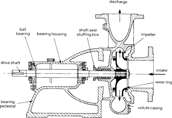
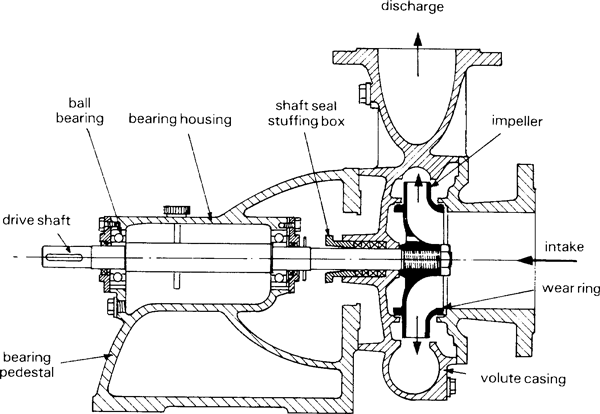
All centrifugal pumps share the following components but their physical configurations may vary:
- Impeller: the physical object that rotates and imparts motion to the fluid. In a car's engine, this would be the equivalent of a piston.
- Housing: provides external walls for the fluid to push against. In a car's engine, this would be like the cylinder.
- Motor: converts the energy source (electric energy, heat from internal combustion) into rotational motion. Without some energy source, the pump won't move!
- Drive Shaft: connects the motor and impeller.
Check out the image below to see these components in action:
 |
| Cutaway view of a compact centrifugal pump. Source: Food and Agriculture Organization of the United Nations |
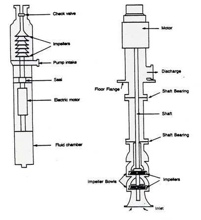
In agricultural operations, irrigation well pumps will tend to be vertical turbine-type pumps. The next image shows a couple of examples of these. Note that the basic pump components are all still present. So the complexity of the pumping system may change, but the basic components stay the same:
 |
| Cutaway view of vertical turbine pump. Source: watertraining.ca |
- For more information about how Wexus' IoT software can drive energy and water efficiency, automation and cost savings for your farming operation, check out our home page here where you can schedule a demo of our software platform or sign up for a free proposal.
- And be sure to follow us for the latest updates and news on Twitter, LinkedIn and YouTube.
